
|
Upconverter
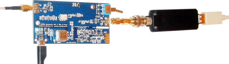
Converts signals in the MF and HF Bands to signals in the VHF Band (approximately 100.5MHz to 150MHz). Intended for use in receiver applications with projects like RTL-SDR/SDR# or FunCube Dongle. The board was designed using the Free and Open-Source Software KiCad and QUCS. All design files are Open Hardware and released into the Public Domain under Creative Commons CC0. There are two versions of this Upconverter that differ only in the LO and IF/Output filters, a 100MHz version and a 125MHz version version. Available from NooElec Online or eBay. KS4JU at HamRadioScience has a review of the board and has posted a tutorial video. Questions or comments? Visit the Opendous Google Group. There is also a FAQ, detailed explanation of the design, and additional testing results. Upconverter in action with DVB Dongle
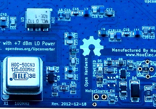
125MHz Upconverter
Only the IF Output filter and LO Filter were updated compared to the previous version.
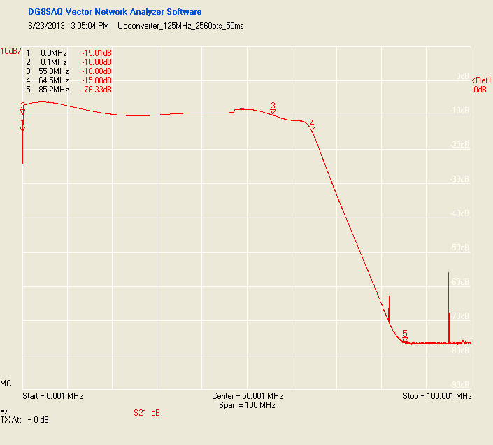
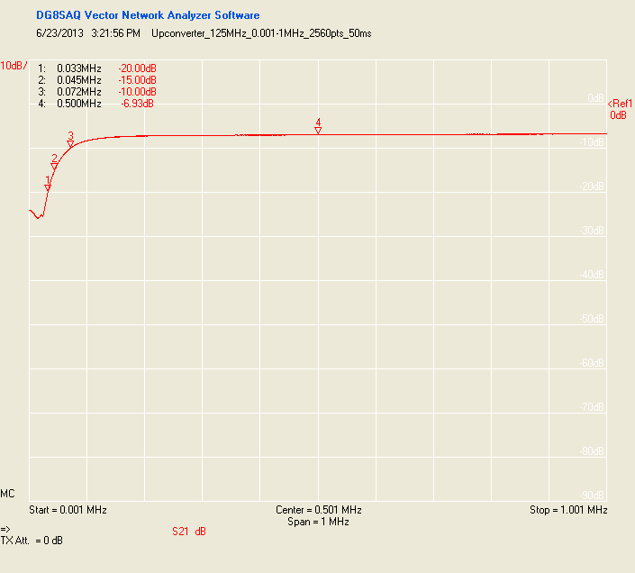
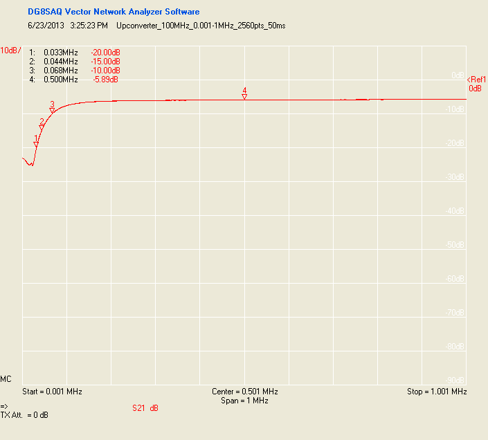
The design files can be found in SVN or downloaded as an archive. 125MHz Upconverter Upconversion LossesThe 125MHz Upconverter has Upconversion Losses (data) of approximately 10dB from 0.1MHz to 55.8MHz and 15dB from 45kHz to 64.5MHz (data). The 1dB compression point is at +1dBm (this is the maximum input signal level before distortion occurs).
100MHz Upconverter
The design files can be found in SVN or downloaded as an archive. 100MHz Upconverter Upconversion LossesThe 100MHz Upconverter has Upconversion Losses (data) of approximately 10dB from 0.1MHz to 48MHz and 15dB from 45kHz to 53.5MHz (data). The 1dB compression point is at +1dBm (this is the maximum input signal level before distortion occurs).
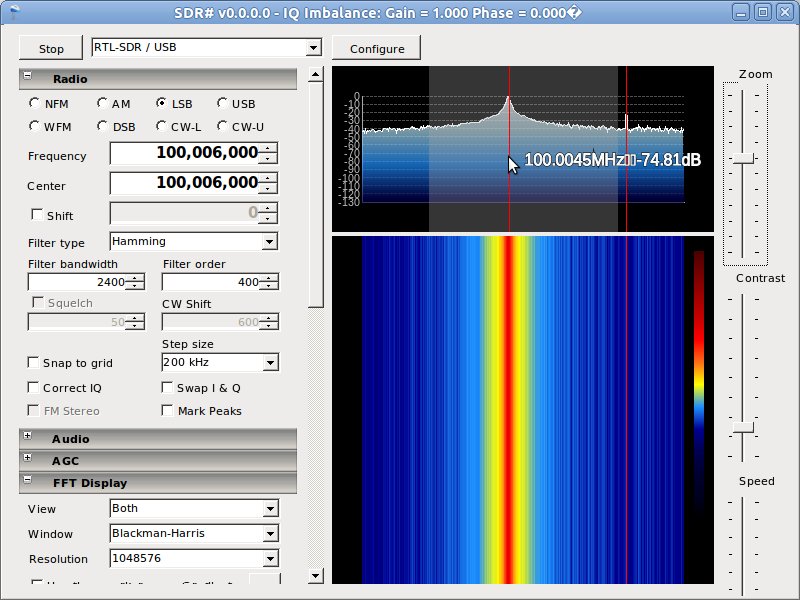
SDR Software Tuning InstructionsWith your Upconverter input shorted or unconnected, tune your SDR software to several kHz above the Upconversion frequency (100.06MHz or 125.06MHz depending on version). Note where the nearest peak is (other than 100.06MHz/125.06MHz where you will see the DC spike) in the FFT display. This value takes into account any frequency offset from the Receiver/Demodulator. Since the 25ppm 100MHz oscillator is likely more precise than the Receiver/Demodulator, subtract the Upconversion frequency from the value to get the Receiver/Demodulator offset (in the picture below it would be 100.0045-100=0.0045). To tune to a Shortwave band such as 9.5MHz, simply add 9.5 to 100 and subtract the offset (9.5 + 100 - 0.0045 = 109.4955). With a high enough SDR sampling speed (0.5MSPS+) you will now be able to make out communication signals you can further tune to.
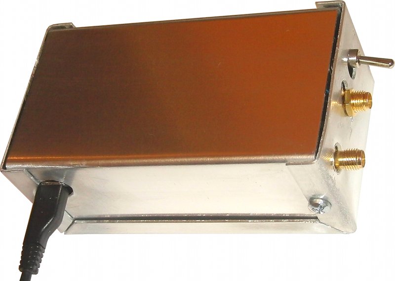
Optional Noise SourceSee Upconverter_NoiseSource for more information. EnclosureSee the Upconverter Enclosure Fabrication Instructions.
FAQCan I connect two receivers to the same Upconverter? : Yes, but the two receivers must have inputs that are compatible with each other. The safest option is to make sure both receivers have no DC feed through a bias tee or disable this option. The receivers could damage each other if one or both have a DC bias. The output of the Upconverter is DC-Blocked so you do not need to worry about it unless dealing with high power levels (> +10dBm). Check out the Upconverter Splitter page. Why not add an amplifier to overcome the 10dB conversion loss? : Since the Noise Figure of an RF system is most dependent on the Noise Figure of the first elements in the signal chain, it does make sense to place an LNA at the antenna port. I just wasn't sure if most users would have their Upconverter at their antenna. Can it be used for Transmitting? : Sure, there are no one-way paths in the Upconverter. If you have a VHF transmitter that operates in the 100MHz to 150MHz range then the Upconverter can be used in reverse as a down-converting mixer to broadcast over 0.5MHz to 50MHz (downconverted 100.5MHz to 150MHz signal). All you would need is a Power Amplifier and bandpass filter for your intended frequency range at the RF port and an attenuator at the IF port if the transmitting signal was above 0dBm. |


► Sign in to add a comment
There is a design flaw in the 125MHz version...
I recently purchased a new upconverter and found that not only did it not work (no oscillator output), IC5 got very HOT. I decided to tackle the project myself.
After troubleshooting against the schematic, I see that pin 1 of X1 is directly tied to ground but actually should be connected to IC8 pin 1 (OSC ENABLE)
If I lift the leg 1 of the oscillator, I then can see 125MHz at leg #5 of the oscillator BUT, I do not see any 125MHz at either IC8 pin 4 or R2 (start of OSC attenuator)
Also, IC5 is VERY HOT to the touch.
I remove the Oscillator DIP socket and find no solder jumps or shorts.
I then focus on IC5. I find that both outputs (pin 4,6 of IC5) are always LOW no matter which position S1 is in. After tracing the board, I remove JP3 (a 0ohm resistor above IC6 (RF IN SW). This disconnects IC8 and removes the short...IC5 now is cold and it's respective pins (4,6) now flip HIGH (3.3v) depending on position of S1
So the problem is somewhere between JP3 and IC8.
The SMA jack for the RF INPUT is the culprit! Upon assembly, there is ZERO CLEARANCE between the ground pins of P1 (SMA jack) and the two traces underneath those pins. The legs of the SMA jack scrape the coating off the PCB and SHORT OUT those traces. Once the SMA jack is removed and the board carefully inspected, normal operation resumes. The problem is ONLY with the INPUT jack.
This is an easy repair. Once can simply use a short pigtail of coax here. In future models, I hope the design team moves those two traces so that they do not lie underneath the back of P1.
The upconverter works VERY WELL. Congrats to the team for producing a fine product.
73, Greg Weremey N1JFE - Electronic Service Pros. http://www.esprepair.com
Hi! I am an employee of NooElec?, the company who manufactures this upconverter design in conjunction with Opendous.
The problem you describe is quite intriguing, as we have produced thousands of these units and have not yet encountered this particular problem in production. The fact that it somehow also made it past our QA team is further cause for concern.
We will be happy to have your board replaced for you (fully at our expense, of course). It may prove beneficial to also get that board back to our lab to try and ascertain the exact reason for the failure. It is likely you are correct, and an out-of-tolerance SMA connector scratched and shorted the PCB, but such boards should certainly not end up in the hands of our customers.
You can reach our support team at support AT nooelec DOT com, or through the contact tools on our website. Thank you for your in-depth analysis and kind words!
>The SMA jack for the RF INPUT is the culprit! >Upon assembly, there is ZERO CLEARANCE between >the ground pins of P1 (SMA jack) and the two traces >underneath those pins
Thank you for the in-depth analysis. Routing under the SMA connector was a compromise to maintain a solid return path for the RF signals. On the vast majority of boards the solder mask is enough to protect the control signals from shorting.
>moves those two traces so that they do not lie underneath the back of P1
That is going to be very difficult. Since the board is 2-layer, there is no easy option to route a control signal without breaking up the return paths for the RF signals. I considered using large (1210) resistors as jumpers but cost constraints reared their head.
RE: Comment by project member [email protected], Jul 15, 2013
Hmm, then perhaps one "fix" is to slip a very small piece of nylon or strong poly in-between the SMA connector body and the pins (or though the resist) that could short out, so that the meager and VERY weak solder resist will still be there and intact, and the nylon or strong poly will both keep abrasions and shorting potential at bay, and should not impede any RF signals.
Although I will try to, I almost never read this area, perhaps any reply can be CC: also to my email OR my Skype ?
Joe Rotello / WindowGroup? / Knoxville, TN Email: joerotello at windowgroup dot com Skype: joerotello
Could the ham-it-up be placed between the antenna and a more sophisticate VHT-UHF receiver to take advantage of the "better" receivers capbilities?
Absolutely the Upconverter can be used with a more sophisticated receiver.
I do believe I have a up converter that is suffering from the shorting of the traces of P1. I cannot get the board to work. Please advise on a return/exchange. Will
The traces under the SMA input connector was the only way I could maintain RF signal impedance on 2-layers and still have a control and power trace running across the RF domain.
It is unlikely that two boards made it out with the same problem. Please check with a multimeter to see if there is a short between Pin1 or Pin5 of IC8 (the SOT23-5 buffer IC next to the oscillator) and Pin3 of IC8 which is GND, same as SMA connector bulk. There should not be. Resistance to GND should be very high for these pins.
If there is a short, please contact NooElec? for an exchange.
Are you just having problems tuning to HAM bands or does nothing work when the Upconverter is plugged in? With power connected and the switch in Passthrough mode, you should at least be able to pick up FM radio with a couple meters of wire as an antenna stuck into the input (unless you live very far from any FM transmitter which would be amazing).
All pins show short on IC8.
I also eliminated the grounds on the RF SMA on the back side just in case they were shorting to the trace there. There did not appear to be any shorting in that area however. Anyway, the thing doesn't work.
I would be happy to return it but if I have to pay the shipping (from Singapore) then the shipping alone is more than the cost including shipping of a new one.
I have an assembled Noise Source which I occasionally use when testing boards and components. Even though it is uncalibrated the Noise is fairly even and broadband. You could use it as a signal source and a RTL DVB dongle as a spectrum analyzer to get a rough sense of the bandwidth of a filter, for example. For serious work I would recommend a VNA.
You could solder a toggle switch to the ENable jumper if you want to be able to turn it on more easily but for some reason the boost converter (SC4503) won't start properly if power is enabled after the Upconverter section is powered. You could try a 1N400x or 1N414x diode in series with the EN jumper to isolate the Noise Source power supply. Possibly an extra high value decoupling cap right after the diode could help.
I have a BladeRF which has a 300MHz lower limit, is it possible to simply change X1 to a higher value or will it need further rework to reach that range? If you could make another version of this up-converter I imagine it would be useful for BladeRF and Myriad owners.
Changing X1 will shift the Upconverted band but the output signal needs to stay within the 121.5MHz to 193MHz bandwidth of the output filter. If you use a 150MHz X1 then the Upconverter will shift 0.1-43MHz (193-150=43) into 150-193MHz so its bandwidth will be reduced.
I have been working on a 300MHz+ based LO version of the Upconverter but creating a cheap and stable LO signal at such frequencies is difficult.
Ok here is a strange issue. My switch is BACKWARDS!
When I switch it to PASSTHROUGH the unit upconverts and when its on UPCONVERT it passes through!!
I was losing my mind trying to figure this out!
Any thoughts on this??
Will
Hold on a second here… I think the markings on the Blue Aluminum case are backwards. After watching the tutorial video I clearly see that the switch position for up convert is towards the IF jack, and looking at the writing on the board it says up convert is down (towards the IF input), however that direction is labeled as PASSTHROUGH on the aluminum box! What the heck?!?!
Will
NooElec? received a bad batch and are selling them at a discount but they do include a disclaimer:
Directly from NooElec?, I purchased and received the NooElec? R820T and 125 MHz upconverter, however, the socket for 100MHz is empty. From what I have been able to find out, there is suposse to be a Oscillator package provided & then that is plugged into the socket. If there is supoose to be a plugin, where or how can I get one?
There should be a Half-Size (8-DIP) oscillator included with the Upconverter that you plug into the socket before using. Note the socket says 100MHz but that is a silkscreen error. The oscillator on the 125MHz Upconverter is 125MHz.
If you are in a hurry DigiKey? can program an ECS-P83-B oscillator for you.
The SGR-8002DC-SCB is also a valid oscillator choice with the same specifications as the ECS-P83. For the 125MHz Upconverter it is optimal to program it to 125MHz=125000000Hz.
Hi ! I have designed and manufactured a enclosure in clear acrylic or mirror acrylic for this board.
Also adapted to the opening for receiving the connector NOISE included in the upconverter wormarts manufacture.(Red board)
I sell on EBAY 360894161534 and AMAZON.
Received my Ham It Up today and no joy. Power Light is on and all connected right but no HF freqs. cant get 20mhz WWV. Any help would be appreciated.
Please tune your SDR software to 125.01MHz or so. Due to how I/Q demodulation works there will be a peak at the center frequency but LO bleed should appear near the tuned frequency at around 125MHz.
Does anything happen when switching between Upconverter and Passthrough mode?
https://groups.google.com/d/msg/opendous/Mn5D2arkukM/G-4cXULeT20J
FWIW - I ordered the kit (NESDR Mini HF (bundle)) on the 1st May 2014.
The Blue case is labelled incorrectly upconvert/passthrough and there was no disclaimer.
I just p-touch taped over it
Just received a HamItUP converter.....no joy.
The 125MHz clock was already installed as shipped from Nooelec, but no HF reception (e.g. even on the AM broadcast band where there are many strong local signals).
Not finding any 125MHz signal, pulled the oscillator and found that the enable wire (e.g. pin 1) was bent at 90 degrees (e.g. not inserted into the socket).
Straightened the wire and reinserted the crystal clock and now hearing some HF signals.
However, only measuring half of the specified 7 dBm signal on the mixer LO port.
Wondering why the converter was shipped in this condition (e.g. manufacturing error, received a returned unit etc.)?
Also have a "Ham it up" that isn't "upping" I'm getting nothing in upconvert mode, not even the big AM stations in town. Certainly not WWV on any of it's frequencies. No bent pins. The LED comes on, but thats it. I'm also not getting any response from their phone or email.
Flipping the toggle switch does nothing? Can you see any signal near 125.01MHz or so? Some LO should be bleeding through.
In passthrough mode, can you receive anything? Like cell tower signals or garage door openers at ~433MHz? http://en.wikipedia.org/wiki/List_of_LTE_networks
>Flipping the switch does nothing? Can you see any signal near 125.01MHz or so? Some LO should be bleeding through.
>In passthrough mode, can you receive anything? Like cell tower signals? http://en.wikipedia.org/wiki/List_of_LTE_networks
>It is possible NooElec? ran out of stock and shipped a refurbished unit. It may have passed all bench tests but re-loosened during transit. Please contact them for an RMA.
>Where are you measuring the LO level? If at the mixer then it would make sense that the signal is being split between the mixer and the measurement device.
Thank you for the above thoughts.
Whether or not NooElec? ran out of stock and shipped a refurbished unit, it clearly did not pass any bench tests prior to shipment or was damaged during transit.
The DOA status was due to the crystal clock having already been incorrectly installed prior to shipment. Specifically, whoever installed it, did so with the enable pin (pin 1) bent over at 90 degrees, which left it unconnected and worst, shorted to case ground, when inserted into the socket. Note: The crystal clock's enable must be connected to Vc (or may float), but will not operate when shorted to ground.
Yes, I measured the LO level at the mixer LO port, because that is where it's specified drive requirement is 7 dBm. Specifically, there would be no power division, as I used a high impedance oscilloscope, then properly converted the peak voltage to dBm @ 50 ohms.
The main reason I purchased the NooElec? up-converter was because it is the Opendous design (e.g. well engineered and extensively inter-stage filtered to prevent spurious mixing artifacts).
I do get ample LO drive at the output of the 6 dB pad. The loss of signal seems due to the bandpass filter between the pad and mixer port, so I'll next try to determine if the correct L-C values were installed, good solder joints (e.g. some appear suspect).
Additionally, I am surprised to hear spurious 108-137 MHz air traffic communications, while listening in the 40M and 75M bands (e.g. see them popping up in the waterfall and when adding the observed HF frequency to 125 MHz, verified to be an in use aircraft band VHF channel). I understand that to eliminate receiving megawatt FM broadcast stations, the LO frequency was changed from 100 MHz to 125 MHz. However, this should not occur, as aircraft transmitters operate at low power (e.g. around 100 W) and the Opendous design has a more than adequate low pass filter on the converter's input (e.g. 66.5MHz cutoff frequency with more than 70 dB of attenuation at 100 MHz).
Aircraft VHF/UHF radios average 9-10 watts average. Thank you. Ed